ZX81 Video Inverter V1
Here are two new
ZX81Video Inverter circuits.
The first design is
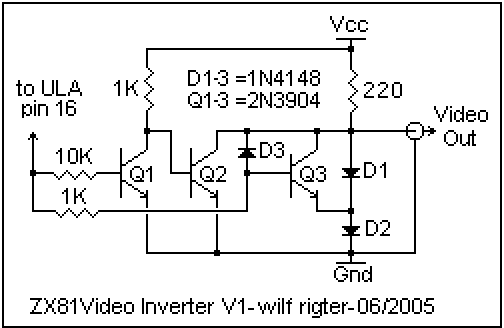
the ZX81 Video Inverter V1 circuit, which uses only
10 discrete
components, is simple to build, draws less that 20mA and
generates crisp white characters on a black screen.

This circuit is connected between the ZX81 ULA pin 16 video output signal
and the RCA jack of the modulator. I usually disconnect and discard the
little PCB inside the modulator to make room. The input pins of the
modulator are connected to the ZX81 motherboard solder pads for ground,
Vcc, TV channel select switch (0V/5V) and composite video. Depending on
The country the composite video signal may be attenuated.
We want to use the full signal from ULA pin 16 which is brought out to a
pad on the ZX PCB
marked UK2. This is a good point for
connecting the
up ZX81Video
Inverter input signal.
The ULA video
signal is 1.8V p-p from white level to sync tip. The black level
is about 1.2V and the screen characters are black on white.
Q1 detects the
sync tip and turns off when the video level is below 0.6V.
This causes Q2 to
turn on and clamp the video output to ground.
When the video input
level is above 0.6V, Q1 turns on, Q2 turns off and the
output signal rises
until D1+D2 clamp the output signal at 1.5V (white level).
When the video input
level is above 1.5V, Q3 turns on and clamps the video
output to 0.8V
(black level). Diode D3 prevent Q3 from saturating which
speeds up video switching times to makes the characters nice and sharp.
The ZX Video
Inverter V1 output is dc composite video, 1.5V p-p from white
level to sync tip
with the black level at 0.8V and screen characters are white
on black. The
inverted Video Out signal can be connected to a monitor input,
with or without a 75
ohm termination, and the inverted Video Output is not
harmed if accidentally shorted to ground.
ZX81 Video Inverter
V2
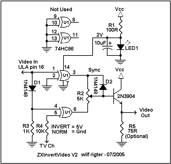
The ZX Video Inverter V2 circuit uses 9 - 11 components including a 74HC86
XOR gate and features selectable Norm/Inverted B/W video characters.

The most interesting part of this design is the use of a reduced supply
voltage for the 74HC86 chip to lower the input threshold to about 1V.
A 100 ohm current limiting resistor (R1) plus a red LED provide a simple
shunt regulator to supply filtered 2V to pin 14 of the chip. The LED
can double as a ZX81 power on indication.
Only two of the four XOR gates are actually used for this circuit.
One gate is used as the sync separator and its output is either sync or
white level. The second gate separates the character data and its output is
either white or black level. These two output signals are mixed into a three
level composite video output signal with sync at 0V, black level at 1V and
white level at 1.4V.
The video signal from ULA pin 16 is about 1.8V p-p. It is normally connected
to the TV modulator, attenuated by resistors and diodes on the ZX81 PCB to
make it compatible with the modulation level required for different countries.
One XOR gate is used as a non-inverting sync separator (pin 2 grounded).
The video signal from ULA pin 16 is connected directly to pin 1 of U1.
When the video
signal on pin 1 is 0V (sync), this causes pin 3 to go low.
When the signal at
pin 1 is most positive (1.8V/white level), pin 3 is high.
When pin 1 is at
black level (1.2V), this is more positive that the threshold
of pin 1 and the
sync separator output on pin 3 is high (data is ignored).
When pin 3 goes low, D2 clamps the base of the output transistor to 0.6V,
which results in 0V sync level at the video output. Resistor R5 is optional
if the monitor input is internally terminated in 75 ohms.
When the ULA pin 16 signal is above the threshold (>1V), the sync separator
output pin 3 goes high (2V) and this signal, through one side of R2 drives
the base of the transistor which drives the video output to white (~1.4V).
The ULA pin 16 video signal is also connected through D1 to pin 4 of the
second XOR gate. This shifts the signal to 1.2V p-p white level to sync tip
with the black level at 0.6V. Since the black level is now less positive
than the input threshold of pin 4, the output on pin 6 of the XOR gate will
switch accordingly when the video data is white or black. The output signal
on pin 6 is mixed with the sync signal from pin 3 the generate the
composite video output signal, using R2 to adjust ratio of sync to black
level to set the contrast. Adjust so that the contrast optimum and minimum
adjust is required for the monitor controls when switching from normal to
inverted video characters.
The data XOR gate is also used to select the normal or inverted video mode
By switching the voltage on pin 5 to 0V or 2V. The VHF/UHF channel select
switch, which has an output of 0V or 5V, can be connected to pin 5 using
series R4 to limit the input current as the 5V output exceeds the XOR gate
internal input protection diode clamping level. If a separate switch is added
to select between ground (0V) and 2V, then R4 may be eliminated.
There it is: two simple circuits to enhance you ZX81 computing experience.
enjoy
wilf